
| |
| Home |
| About JKC |
| Coating Library |
| Designs |
| Materials |
| Designer FYI |
| Classes |
| Links |
| Contact Us |
High Reflector Coatings (HR) - is a film or system of films deposited on a substrate to increase the overall reflectivity of the substrate surface.
HR's primary function is to increase the reflectivity of a substrate surface, and in most cases, move or steer the light to another location in a optical system. HR's are divided up into two basic areas: Metals and Dielectric Multilayers. Metal coatings are widely used to steer light in an optical system and, in most everyday uses, are thr more economical reflector alterative. Metal coatings can be extremely broadband, but have a tendency to be fragile and hard to clean. Dielectric films are used for more narrowband applications where high reflectivity, low absorptivity, and robust coatings are necessary. This section of Optical coating design will be divided up into 2 areas:
Metal mirrors have been made for centuries and are fairly common in many optical systems. The mirror's main purpose is to collect light and steer it to another location in the optical system. Metal mirrors offer high efficiencies and are the coating of choice for very large optics, such as telescope mirrors. However, their drawback is that they are extremely fragile and difficult to maintain over long periods of time. The most common metals used for highly reflective surfaces are Aluminum (Al), Gold (Au), and Silver (Ag). Their reflective performances are shown in the figure below:
Here are just a few notes on each of these three popular metals:
| Metals | Average % Reflectivity Vis / IR |
Regions of high Absorption | Comments |
| Aluminum | 92 / 98 | 700-950nm | Sensitive deposition parameters necessary to prevent
"Blueing" (scatter in visible). Thin layer of Al2O3 forms on surface. |
| Gold | 94 / 98 | 300-550nm | Adhesion issues with glass. Very soft surface. Use Chrome as binderlayer. |
| Silver | 95 / 98 | UV | Issues with tarnishing. Very soft surface. |
There are also other metals that are used frequently as mirrors. The figure below outlines the refelctance performances of Copper (Cu), Nickel (Ni), Platinum (Pt), and Rhodium (Rh).
THE INDEX DATA FOR ALL OF THE ABOVE METALS CAN BE FOUND ON THE MATERIALS PAGE.
Most metal thin films are suscepible to damage if cleaned or wiped. Therefore, in most cases, it is necessary to protect the metal film with some type of transparent dielectric layer to increase the mirrors robustness. The figure below shows the optimum thicknesses for the dielectric film layer that would produce maximum and minimum reflectivity when the design wavelength was 550nm.
Protective layers not only need to have their thickness optimized, but their index needs to be as low as possible for broadband higher reflectivity. The figure below outlines the difference between a film with an index of 1.45 and one with and index of 2.0. The minimums on the curve for the film with the 2.0 index are lower than that of the 1.45 film. Therefore, if the only protective film alternative is one with a high index, care needs to be taken to be sure that the optical thickness is at the reflectivity maximum. If the optical thickness is missed, reflectivity will be sacrificed.
Another important point to remember when designing a protected metal mirror is that with the addition of a dielectric layer, within a region where the metal has absorption, the metal absorption increases at non-normal incidence. The figure below shows the effect of a protective layer of n=1.45 on aluminum where the incident angle is 45 degrees:
Enhancing the reflectivity of a metal layer will not only boost the reflectivity around the design wavelength, it will also narrow the high reflectivity region. When starting the design for the enhancement layers it is important to have the low index layer closest to the metal and the high index layer closest to the medium, as shown:
Medium / (H L)m Metal /
Substrate
where m is the number of repeating periods of HL
The figure below shows an enhanced aluminum with a high index of 2.40 and a low index of 1.46. As one can see, by increasing the number of periods, the reflectivity increases, but the high reflectivity region narrows.
The Basic HR
The high reflector design is based on alternating high and low refractive index layers, nH and nL such that a "stopband" (or area of high
reflectivity) is created that is centered around the design wavelength, l0. The most basic HR design has each layer arranged such that the optical thickness of
each of the indiviual layers equals a quarter of the design wavelength, or a QWOT.
The design in its basic form resembles:
Medium / (HL)m H / Substrate
where m is the number of periods of the multilayer stack.
The following figure below outlines all of the characteristics of a basic (HL)mH high reflector design
From the figure above one can see that the high reflector has a 1st order harmonic stopband and successive harmonic ordered stopbands at lower wavelengths. In between the harmonic stopbands is an area know as the "passband" where light is transmitted and not reflected. One will also notice that for this basic design there are no 2nd or 4th order stopbands. Later in this tutorial, determining your harmonic stopbands will be addressed.
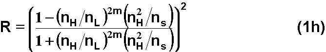
If you have designed your HR to be of the period m and desire to know what the reflectivity of the system will ultimately be the following formula to calculate the reflectance, R, is the following:
Now, if you have a specific reflectivity in mind, and want to know how many periods to start with in your design, you can use the formula below solved for the period m:
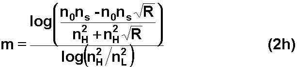
So, for example, if we are building a HR on glass (ns=1.52)with nL=1.46 (SiO2) and nH=2.40 (TiO2) at l0=550nm, and we wanted to have a reflectivity of 99.9%. If we use equation-2h above, m=7 periods. The example is shown in the figure below:
Air / (HL)7 H / Glass
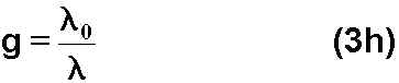
There will also be some variables used to describe the stopband of the high reflector. The first is g which is the ratio of the design wavelength to the performance wavelegth, where,
And, the half-width of the stopband Dg , where,
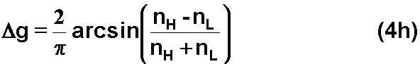
The stopband can be described Dg when the spectral performance is viewed in terms of g:
The most interesting phenomenon associated with high reflector designs is the reflectivity profile at other wavelengths other than the design wavelength. The peak that is created from the QWOT layers at the design wavelength is referred to as the first order harmonic. We have seen in a figure above that for the basic high reflector stack their are also higher order harmonics that have high reflectivity as well. This section of HR design is going to cover deisgn modifications to the basic HR to manipulate which higher order has high reflectivity or is highly attenuated. The technique used is referred to as a ratio stack.
A traditional HR design has both of the high and low index layers at perfect QWOT at the design wavelength. Therefore, the low to high index ratio is 1:1. If we alter the ratios of the high index layer to the low index layer we can alter which higher orders will be present and which ones will be suppressed. The figure below shows the performances of a 1:1, 2:1 and 3:1 high reflector stacks when plotted vs. g:
The figure below was taken from Philip Baumeister's lecture notes and illustrates when stopbands and passbands occur for a 1:1, 2:1, and 3:1 ratio stacks.
The above figure illustrates that in the different ratio designs, if the edge of the shaded area falls in the center of a wave, the order will have maximum reflectivity. If the edge of the shaded region falls at a nodal point, there will be no reflection band at that order. If the edge falls within the wave but not at the center, the reflection band will be present, but not at maximum reflectivity.